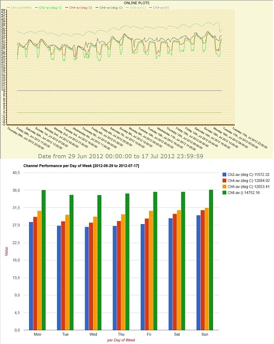
A free service to present real-time and historical data of Symmetron data loggers on the World Wide Web, with plots and statistics for each measuring station.

For more information about Captum service, click here.

For a free demonstration, click the Enter button below and login as a visitor, with user name Symmetron. View the site named Office Temperature

 Åßóïäïò


Subscribe to our mailing list

* indicates required


Home Contact Us

English Greek
   
    QUESTIONS

Low level AC anemometers (like the popular #40) are using a rotating magnet passing near a fixed inductor to convert rotary movement to an AC voltage.
This construction is simple and efficient. However, there are some side effects:
When the anemometer is hit it acts somewhat like a microphone: it produces spurious output that can be mistaken as increased wind speed. This is the case with a hail storm.

It is recommended to use shielded cables for connection of sensors to the datalogger. Connect the lower end of the shield to the GROUND terminal of the datalogger. Thus, you avoid possible electromagnetic interference.
The time stamp is recorded at the end of the averaging interval i.e. each line of the decompressed file has the time stamp that refers to it.
The "NO MODEM" message appears or the modem is not registered in the GSM network. The LED is continuously flashing. Possible reasons why this may be happening are the following:

1. The modem has no signal
2. It has no SIM card
3. It has a SIM card but it has not been placed correctly (if the drawer has been placed amiss, the card is not recognized)
4. Especially for the "Wavecom Fastrack Supreme" modem: It has a SIM card but the black switch on the edge of the card's reception is not closed.
5. The SIM card is locked, it has a PIN, and it must be unlocked (via a mobile phone or the datalogger's UNLOCK PIN menu).

COMMUNICATION IS ONLY POSSIBLE when the modem LED indicates succesfull network registration: OFF for 2-3 seconds, ON for half second.
The rain gauge must be connected between Cx and +5V FIXED (wire polarity does not matter). The input type must be REED. Only the metal enclosure must be connected to GROUND.
If the datalogger has a password, the user must set the same password in the corresponding site's properties.
In the case of Set-10 (Stylitis-10), this can be set via the "Communication|Communication Settings" menu, while in the case of Stylitis Explorer (Stylitis-40 or Styitis-100), this can be set via the "Site|Site Properties" menu, in the "Password" field.
The mast must always be grounded. Instrument cable shields must be connected to GND on datalogger's screw terminals. For better instrument protection of stand-alone systems it is recommended not to connect the datalogger's external ground screw to the grounded mast (that is leave the measuring system isolated).
CAUTION: The datalogger must always be grounded if it connected to any external system (i.e. computer, mains power supply, etc.)

It is very important for the lightning rod to be placed high enough, so that the angle between its horizontal boom and the line which connects the lightning rod's top with the top anemometer is at least 60 degrees.

In case a sensor is destroyed by lightning, despite the measurements taken, and the corresponding input of the datalogger does not function, it is possible that only the input's GND is cut. Therefore, it must be checked via a multimeter if the GNDs of the datalogger are connected.
There is the opportunity for the actions selected in a connection's properties, via AutoConnect or Stylitis Explorer or Set-10, to be executed not only once a day, but every one specific interval from the time of the first connection (the time defined in the "AutoTime" cell). This can be done if the user sets "RetryTimes" =999 or greater, for the desired connection, while the connection will always be repeated after the number of minutes which the user has defined in the "RetryInterval" cell. The process is repeated to infinity, even if the day changes (with the difference that then, the actions of the next day are executed) until the user changes the value of the "RetryTimes" cell.
1. Visit the website: www.ftdichip.com/Drivers/VCP.htm
2. Select the Driver Version (corresponding column) 2.04.xx. It is recommended that the "setup executable" version is selected (from the corresponding link in the "Comments" column)
When creating a new connection in a site folder, its default name contains the site's name and the consecutive number of the connection in the folder. However, if the user desires to change the connection's name, they must pay attention to what they select, because if the connection is automatic and it has the name of an existing one, AutoConnect will locate only the new connection. This is happening because the connections' names registered in the computer are unique, therefore a new connection with an existing name will replace this older connection in the computer's Registry.
1. Connect DIGI to your network and to the datalogger via a 1-to-1 cable.
2. Install DIGI's software and use Device Discovery to find its IP address.
3. Open the Web Interface and type
Username:root and Password:dbps.
4. In the 'Configuration|Serial Port' menu select profile: 'TCP Sockets'.
5. In the 'Serial Port Configuration' window, set Raw TCP Port: 2101 (default).
6. In the 'Basic Serial Settings' paragraph, set Baud rate:9600, data bits:8, Parity:none, Stop Bits:1 and Flow Control: None.
7. Press 'Apply' and close the Web Interface by pressing 'Logout'.
8. Adjust the Ethernet connection's properties in Stylitis Explorer with the IP address and the Raw TCP Port that were mentioned above.
9. Start the connection in Stylitis Explorer by pressing 'Connect' and then 'WakeUp'.

Select 'Regional and Language Options' from the Control Panel and check if the same language (e.g. English (United States)) has been selected in the fields that are located:
a. In the 'Standards and formats' section, in the 'Regional Options' tab and
b. In the 'Language for non-Unicode Programs' section, in the 'Advanced' tab.
In the "Show Connections" window, in the "Connections" tab, the available automatic connections appear, sorted in priority order. On the upper part of the list, the connections with the highest priority are located. By double-clicking on the top of a column in this tab, the connections are sorted in alphabetical order, according to this column, but this sorting is temporary and it is done for optical reasons. However, if the icon (A->Z), in the lower left part of the tab, is pressed, the connections are sorted according to their name, and the sorting is permanent, that is the priority order of the connections changes.
A) In case you are using Microsoft Office 1997-2003:

1. Open the .DXT file with Excel. Excel will automatically recognize the file format (columns separated with spaces) and will present a file import wizard for assistance.
2. In the first wizard step enter 25 in the 'Start import from line' box and click next.
3. In the second step create vertical lines, by clicking between the columns, to separate all columns except Date and Time which should be grouped together in a single column.
4. In the third step click finish. Excel will import the data file.
5. Widen the first column (date/time) and select the top left cell.
6. On the Toolbar click on the Chart wizard. Select the 'XY(Scatter)' plot type and click 'Finish' (or click next to customize plot appearance).

Â) In case you are using Microsoft Office 2007:

1. Open Microsoft Excel. In the 'Data' tab, select `Get External Data` and `Text File`from the pull-down menu. Then, a browser will appear for the user to search the datalogger's site folder.
2. Open the folder and select 'File types : All files', because the .dxt files are not recognized as text files. Select the desired data file.
3. In the appearing wizard, in the first step, in the 'Start import from line' box, insert 25 and press 'Next'.
4. In the second step, create vertical lines, by clicking between the columns, to separate all columns except Date and Time which should be grouped together in a single column.
5. In the third step click finish. Excel will import the data file.
6. In the appearing window, select the top left cell (default) and click OK.
7. In the 'Import' tab, select 'Scatter' as plot type and, via the pull-down menu, select the graph format.
A) In case you are using Microsoft Office 1997-2003:

1. Open the stXXXXXX file with Excel. Excel will automatically recognize the file format (columns separated with spaces) and will present a file import wizard for assistance.
2. In the first wizard step enter 15 for Stylitis-41 or 33 for Stylitis-101 in the 'Start import from line' box and click 'Íext'.
3. In the second step create vertical lines, by clicking between the columns, to separate all columns except Date and Time which should be grouped together in a single column.
4. In the third step click finish. Excel will import the data file.
5. Widen the first column (date/time) and select the top left cell.
6. On the Toolbar click on the Chart wizard. Select the 'Lines' plot type and click 'Finish' (or click next to customize plot appearance).

Â) In case you are using Microsoft Office 2007:

1. Open Microsoft Excel. In the 'Data' tab, select `Get External Data` and `Text File`from the pull-down menu. Then, a browser will appear for the user to search the datalogger's site folder.
2. Open the folder and select 'File types : All files', because the stXXXXXX files are not recognized as text files. Select the desired data file.
3. In the appearing wizard, in the first step, in the 'Start import from line' box, enter 15 for Stylitis-41 or 33 for Stylitis-101 and press 'Next'.
4. In the second step, create vertical lines, by clicking between the columns, to separate all columns except Date and Time which should be grouped together in a single column.
5. In the third step click finish. Excel will import the data file.
6. In the appearing window, select the top left cell (default) and click OK.
7. In the 'Import' tab, select 'Lines' as plot type and, via the pull-down menu, select the graph format.
In case of any problem, for your better service, select 'Options' from the pop-up menu and open the 'Reports' tab. Click the 'Monitor.txt' file, which can be seen in the window's lower part. In this file, the activity of all connections checked and attempted by AutoConnect every 30 seconds is recorded. You can send it to us via email, so that we can locate any problem which may occur, more effectively.

NOTE: This file records the activity mentioned for every opening of AutoConnect. That is, with a Restart of the program, the file is lost and it is recorded from the beginning.
Stylitis-10 and Stylitis-Power dataloggers connect to the Ethernet via a Digi Connect ME module. The user selects ¡Communication | Find logger in LAN¢ from Opton¢s menu to locate the datalogger. Actually, the Digi discovery utility is started which searches for the Digi module in the local LAN.
If the Digi module is set to a fixed IP address in a different subnet then the Digi Discovery utility cannot locate the module.

Symptom: When the ¡Refresh view¢ option is selected in the ¡Digi Device Discovery¢ window, the green LED on the Digi module flashes but the Discovery utility fails locating the module.

This procedure can be used to find the Digi module¢s IP address and restore it.

o Install and run the freeware Wireshark network sniffer.
o Next to ¡Filter¢ text box click ¡Expression…¢.
o In the ¡Field name¢ box find ¡Ethernet – Ethernet¢ section and click ¡eth.addr¢.
o In the ¡Relation¢ box click ¡==¢.
o In the ¡Value¢ box enter the Digi MAC address as XX:XX:XX:XX:XX:XX
o Click OK.
o Next to ¡Expression¢ and ¡Clear¢ click ¡Apply¢. Wait for the filtering to be completed.

o Connect the Digi the local network, power up and allow 1 minute for booting up.
o In Wireshark, select menu Capture | Interfaces, select the Ethernet interface and click ¡Start¢.

o In Opton select Communication | Find logger in LAN (Alternatively, run standalone Digi Discovery utility).
o In Wireshark upper pane Digi broadcasts are shown. In the ¡Source column¢ you can locate the Digi IP address (For example: 10.150.0.201).

o Disconnect PC and Digi from LAN. Using a cross-over UTP cable connect Digi and PC.
o Set a PC IP address inside the Digi subnet (For example: 10.150.0.100). Open the control panel and select ¡Network Connections¢. Right click on ¡Local Area Connection¢ and select ¡Properties¢. In the ¡General¢ tab, double-click ¡Internet Protocol (TCP/IP)¢. Select the second radio box and type this IP address in the first field.
o Again, select in Opton ¡Communication | Find logger in LAN¢ (Alternatively, run standalone Digi Discovery utility). This should find Digi.

o After locating Digi with the Discovery utility select ¡Configure network settings¢ under ¡Device tasks¢. In the Settings window select ¡Obtain network settings automatically¢ and ¡Save¢.
o Click ¡OK¢ in the ¡Restart device¢ message box.

o Restore PC IP settings for LAN operation and connect both PC and Digi to the LAN.


------------------------------------------------------------------------------------------------------
Stylitis-10 and Stylitis-Power are trademarks of Symmetron Electronic Applications
Digi and Digi Connect ME are trademarks or registered trademarks of Digi International Inc. in the United States and other countries worldwide.
Wireshark is a registered trademark of the Wireshark Foundation
Open the AutoConnect main window and select the Connection Properties tab.
Scroll right and locate the CloseFile column. Select 'YES' for the connection name you want and click the OK button.
When you connect via GPRS (to Stylitis-10, to the Sym-o-net or to Stylitis-Power), the data exchanged are charged to the SIM card of the datalogger or the Sym-o-net. On the contrary, via a data call the SIM card of your computer's modem is charged via time charge.
For full instructions, click here.
CATEGORIES